【Scope of application】
This bundle wire and cable burner is produced in strict accordance with GB/T18380.31-2008, equivalent to the IEC60332‐3‐10:2000 standard, which is used to evaluate the ability of vertically installed bundle wire and cable or optical cable to suppress the vertical spread of flame under specified conditions, and is economically applicable and widely used by the wire and cable industry.
【Relevant Standards】
GB/T18380.31-2008, IEC60332‐3‐10:2000
【Scope of application】:
This bundle wire and cable burner is produced in strict accordance with GB/T18380.31-2008, equivalent to the IEC60332‐3‐10:2000 standard, which is used to evaluate the ability of vertically installed bundle wire and cable or optical cable to suppress the vertical spread of flame under specified conditions, and is economically applicable and widely used by the wire and cable industry.
[Meet the standard]:GB/T18380.31-2008, IEC60332‐3‐10:2000
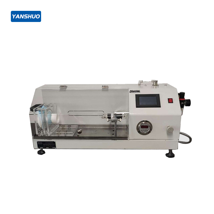
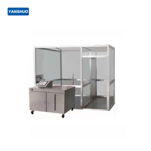
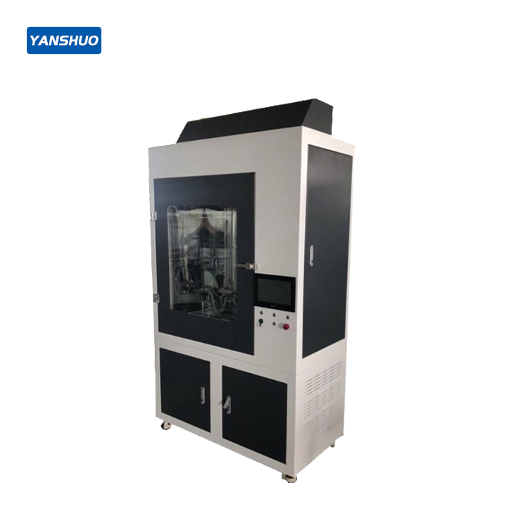
[Instrument features]:
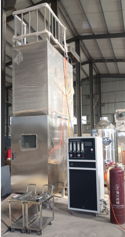
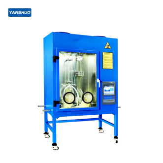
The experimental device is a self-supporting box with a length of 2500mm, a width of 3200mm and a height of 4500mm, and the bottom of the box rises above the ground. The perimeter of the test chamber is sealed, and the air opens an 800mmX400mm air inlet from the bottom of the box 150mm from the front wall to flow into the chamber. A 300mm ×1000mm air outlet is opened at the back of the top of the box. The back wall and both sides of the test chamber are thermally insulated with a heat transfer coefficient of about 0.7W∙m-2∙K-1, the distance between the steel ladder and the back wall of the test chamber is 150mm, the bottom of the steel ladder is 400mm from the ground, and the lowest part of the cable specimen is about 100mm from the ground.
【Technical Parameters】:
1. Combustion chamber part:
1. Shape (overall space) size: 2500mm (length) * 3200mm (width) * 4500mm (height)
2. Material: thermal insulation with a heat transfer coefficient of 0.7W∙m-2∙K-1, that is, a stainless steel plate covered with 65mm thick mineral fiber
3. Air source: control the gas flow rate through the box to (5000±500) L/min, and the air flow rate can be stabilized during the test. A spraying device that forcibly stops burning after the test is completed
4. Steel ladder type: 500mm wide standard steel ladder 800mm wide steel ladder
5. Discharge purifier device: The test chamber has a device for collecting and washing smoke and dust that will not change the air flow through the test chamber
6. Ignition source: including one or two belt propane gas blowtorches and their supporting flow meters and venturi mixers. The fire supply surface should be drilled with 242 flat metal plates with a diameter of 1.32mm, the center distance of these holes is 3.2mm, and they are arranged in three rows of staggered arrangements, each row is 81, 80 and 81 respectively, distributed in the range of 257×4.5mm in nominal size. In addition, a row of small holes are drilled on each side of the flamethrower, which can maintain the stable combustion of the flame.
a. Each blowtorch is equipped with a rotor flow meter to accurately control the propane and air inflow rate.
b. Under the reference conditions of 100kPa and 20°C, the airflow rate of the test is as follows:
Air (77.7±4.8) L/min Propane (13.5±0.5) L/min
7. The location of the ignition source: the blowtorch is placed horizontally, (75±5) mm away from the front surface of the cable specimen and (600±5) mm from the bottom of the test chamber, and symmetrical to the axis of the steel ladder. The blowtorch fire supply point should be located in the center between the two rungs of the steel ladder and at least 500mm away from the lower end of the specimen
8. Observation window: one tempered glass observation window, surrounded by stainless steel edging
9. Exhaust system: 2 spiral exhaust fans, sealing push and pull plate 2.0mm stainless steel
10. Air inlet: 1 (ф160mm) 11. Bottom fixing frame: made of 40mm*40mm square pass
2. Control part:
Note:
1. Air flow adjustment: adjust the test air flow, about 77.7L/min under the reference conditions of 100kPa and 20°C;
2. Gas flow adjustment: adjust the test gas flow, about 13.5L/min under the reference conditions of 100kPa and 20°C;
3. Air pressure display: test air pressure display;
4. Gas pressure display: test gas pressure display;
5. Air pressure adjustment: adjust the intake air pressure;
6. Gas pressure adjustment: adjust the inlet gas pressure;
7. Temperature display: test temperature monitoring display;
8. Temperature display in the box: temperature display inside the combustion box;
9. Combustion time: set the combustion time applied to the specimen according to the standard requirements, when the instrument starts the ignition, it will start the timing immediately, and after the set time arrives, it will naturally jump to the reigniting time timer, and the reigniting timing will run automatically; 0-99.99S/M/H arbitrary setting;
10. Reignition time: When the combustion time arrives, the reigniting time timer starts running until the specimen flame is extinguished naturally, there are no falling objects or all objects have no open flames, press the “reignition pause” button, the time on the timer will be fixed on the display, and the recorded time will be recorded as the reignition time;
11. Reignition pause: Press “Reignition Pause”, and the timing time on the reignition timer will be fixed on the instantaneous time at this time.
12. Ignition: set the burning time according to the standard requirements, press the “ignition” button, ignite the igniter, light the blowtorch, and the flame is applied to the specimen to start burning;
13. Stop: press the “stop” button to stop the blowtorch from burning the flame, and the timer is fully reset;
14. Power supply: the power supply is AC220V 50HZ, connect the power cord to the power supply, turn on the power switch, and start the instrument;
15. Circulating water pump: press the “circulating water pump” button, the pumping water pump runs, and the water tower carries out exhaust gas filtration treatment;
16. Fan: exhaust fan operation;
17. Single and double blowtorches: single blowtorch and double blowtorch switching options.
3. Test part
1. Combustion test chamber 2000mm (length) * 1000mm (width) * 4000mm (height)
2. 2 belt propane gas blowtorches (as shown in the picture)
3. Standard steel ladder with a width of 500mm and a steel ladder with a width of 800mm
4. 1 370W single-phase water pump
5. 1 internal flame contact point indicator ruler
6. 1 paper size ruler
7. Test length ruler 1
8. Test fixing frame: material: steel plate is finely processed and painted, pure black
【Precautions】:
1. Before the test, connect the pressure regulator for the hose of the liquefied petroleum tank, then connect the signal control line, connect the power switch of the control box, check that the connection is correct, and pay attention to whether there is air leakage. If there is no air leakage, the power switch can be turned on to the open position. Open the main valve of the cylinder, unscrew the pressure regulator switch, the pressure indicated by the high pressure gauge of the acetylene pressure reducing valve should be 0.01~0.02Mpa (this is the working pressure of the outlet), if it exceeds 0.02Mpa, it will be dangerous, and there may be air leakage.
2. After the test, the power switch and the main valve of the gas cylinder should be turned off to confirm that there is no fire from the combustible material before leaving the site.
Test method:
1. Sample selection
a The specimen shall consist of several cable specimen segments of equal length. The minimum length of each cable specimen segment is 3.5m
b The total number of roots of the cable specimen section should be the non-metallic material contained in the specimen in the total volume
c Specimens should be selected within the range specified in Table (1).
d The cable specimen section used as a specimen before the test should be placed at (20±10°C) for at least 16 h. The cable specimen segment should be dry.
2. Determination of the number of cable specimen sections
a is the number of cable specimen segments to be calculated. The volume of non-metallic materials contained per meter of a cable specimen section should be determined.
b Carefully cut a cable segment not less than 0.3 m. Its section is at right angles to the cable axis so that its length can be accurately measured.
c The density of each non-metallic material (including foamed material) should be measured by appropriate methods, and the measured data should be about 2 decimal places.
d Peel off each non-metallic material C from the cable segmentiWeigh them all. Any material less than 5% of the total mass of the non-metallic material should be assumed to have a density of 1 kg/dm3
e If the semiconductive shield cannot be stripped from the insulation. It can be regarded as a single measurement of mass and density.
Each non-metallic material CiThe volume of Vi ( I. /m cable) calculated according to the following formula:
Among them:
Mi— Material Cimass in kilograms (kg);
pi— Material Cidensity in kilograms per cubic decimeter (kg/dm).3);
l– Length of cable specimen segment in meters (m)
The total volume V of non-metallic materials contained per meter of cable is equal to the volume V of various non-metallic materials1,V2etc.
Divide the volume per meter specified in the test standard by the total volume V of non-metallic materials per meter of cable to get the number of cable specimen segments to be installed. Take the nearest whole number (rounded up to 1 above 0.5) and install it on the steel ladder.
3. Specimen installation
1) Some sections exceed 35 mm2cable
For at least one conductor with a section of more than 35 mm2The cable. Each cable specimen section should be fixed on each rung of the steel ladder using metal wire (steel wire or copper wire). Cables with a diameter of 50mm and below should be made of 0.5 mm~1. 0 mm metal wire. Cables with a diameter of more than 50 mm should be equipped with a diameter of 1.0 mm~1. 5 mm metal wire.
The cable specimen section should be installed in a single layer in front of the steel ladder. The spacing between the cable specimen segments should be 0.5 times the cable diameter. But no more than 20 mm. Whether it is a standard steel ladder or a wide steel ladder. The minimum distance between the edge of the specimen and the inner vertical surface of the steel ladder should be 50mm
The maximum width of the specimen on the standard steel ladder should be 300mm. The maximum width of the specimen on the wide steel ladder should be 600mm.
When installing the cable specimen section. The first cable specimen section should be roughly located in the center of the steel ladder. Subsequent cable specimen segments are added on both sides. So that all cable specimen segments are roughly arranged in the center of the steel ladder.
For AF/R cable installation using standard double-layer spacers, please refer to Table 1 for specific operation
During installation, each cable specimen section should be fixed on each rung of the steel ladder using metal wire (steel wire or copper wire). Cables with a diameter of 50 mm and below should use metal wires with a diameter of 0.5 mm~1.0 mm. Cables with a diameter of more than 50 mm should be equipped with a diameter of 1.0 mm~1. 5 mm metal wire.
Using a standard steel ladder, the specimen should include at least 4 cable specimen segments. At least two cable specimen segments should be installed behind the steel ladder.
When the specimen requires more than 4 cable specimen sections, the cable specimen sections installed successively should be installed alternately in front of and behind the steel ladder.
The whole specimen should be installed as follows:
– The spacing between cable specimen segments in the first layer (front or back) should be 0.5 times the cable diameter, but not more than 20 mm;
– The maximum width of a single layer should be 300 mm;
—The minimum distance between the edge of the specimen and the vertical surface on the inside of the steel ladder should be 50 mm;
– The cable specimen section installed behind the steel ladder should be located in the center of the interval between the specimen sections in front of the steel ladder;
—All cable specimen segments are roughly arranged in the center of the steel ladder
2) Some sections are 35mm2and below
For some cables with a conductor section of no more than 35mm. The cable specimen section should be separately or in groups with a diameter of 0.5 mm~1. 0 mmmm metal wire (steel or copper) is fixed to the individual rungs of the steel ladder.
The cable specimen section should be installed in front of the standard steel ladder in one or more layers in contact with each other, and the maximum width of the specimen should be 300mm. The minimum distance between the edge of the specimen and the inner vertical surface of the steel ladder should be 50mm.
When installing the cable specimen section. The first cable specimen section (group) should be roughly located in the center of the steel ladder. Subsequent cable specimen segment suction group) is added on both sides. So that all cable specimens are roughly arranged in the center of the steel ladder.
If the first (or later) floor uses up the full width of the steel ladder. A second (or more) layer is also required. The first cable specimen segment of the second (or later) layer should be roughly located in the center of the steel ladder. Subsequent cable test section core group) is added on both sides. So that all cable specimen sections of the second [or later] layer are roughly arranged in the center of the steel ladder.
If the specimen requires a large number of cable specimen segments. The specified metal wire can be used to form a flat cable specimen segment group and be installed on the steel ladder rung. The maximum width of each cable specimen segment group is 5 cable specimen segments. To ensure consistency. It is recommended to secure adjacent cable specimen segments to each rung tightly together. Ensure that the cable specimen segments are in contact with each other
(Standard steel ladder single-layer contact installation)
4. Fire supply time
The fire supply time for AR/F, A, B cables is 40 minutes, and the fire supply time for C and D cables is 20 minutes, after which the flame should be extinguished. The flow of air through the chamber should be maintained until the cable stops burning or glowing. or maintain it for a maximum of 1 h. After that, the burning or luminescence of the cable should be forcibly extinguished.
5. Evaluation of test results
After the cable stops burning or glowing or is extinguished. The specimen should be wiped clean. Wipe after cleaning. If the original surface is not damaged. All soot is negligible. Softening or any deformation of non-metallic materials is also negligible. Flame spread should be measured by the extent of the damage. The damage range is the distance between the bottom edge of the blowtorch and the starting point of the carbonization part, in m, accurate to 2 decimal places. The starting point of the carbonization part is determined as follows:
Use sharp objects. For example, when pressing the surface of the cable, the place where the surface changes from elastic to brittle (powdered) indicates that it is the starting point of the carbonization part.
6. Performance requirements
The performance requirements for specific types or types of wires and cables should be separately specified in the relevant cable product standards. In the absence of a given performance requirement, that is, in front of or behind the steel ladder, the maximum carbonization range of the measured specimen should not be higher than 2.5m above the bottom of the blowtorch.
7. Re-inspection steps
The specimen failed this test. When there is a dispute. Two more tests should be conducted according to the above provisions. If both test results meet the described requirements. The wire and cable should be considered to have passed this test.
8. Test report
The test report should include the following information:
i Full description of the cable under test;
j The manufacturer of the cable under test;
k Perform the standard part of the test reference;
【Installation Conditions】:
Space requirements:
1. Overall dimensions: Dimensions: Width 2500mm, depth 4500mm, height 5500mm
2. Weight (KG): about 205 tons
3. Test bench: length not less than 6 meters high * 5 meters * 5 meters
Power Requirements:
1. Voltage: 220V±10%, 50HZ
2. Power: 7KW
Water Source:
The cooling water source is equipped with supporting sewage discharge
Air source:
Industrial propane/3kw air compressor, flow rate not less than 300L per minute
Contaminant description:
Smoke and dust
Ventilation requirements:
Do flue gas collection and connect to the flue gas treatment and purification system
Other test requirements: gas cylinders are equipped with pressure reducing valves, equipment is large, and it is necessary to bring its own forklift of more than five tons to unload
A crane is required for lifting, and three sets of scaffolding are also needed to be about five meters high